PuzzleBot
Overview
The mechanical system consists of a four axis gantry designed to be used as a pick-and-place, with a structural frame for mounting an overhead camera. The rotating head uses a vacuum pump to lift the pieces using suction.
Renders
The Completed System
Challenges
We had many problems with 3D printed parts breaking under the stress of operation (seen below). This was because many parts were printed with minimum infill and shells to reduce print times and material consumption. Some of these parts were machined out of metal to make them stronger; others were reprinted with stronger settings.
The motors we had available for the short axis turned out to be too weak to move at the desired speed. We solved this problem by adding a second motor to the axis to increase torque.
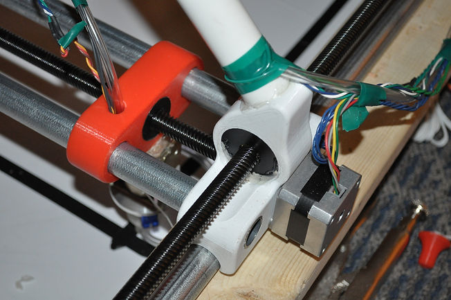
We had a problem with aligning the leadscrews, since the leadscrews are technically over constrained if they are fixed at both ends (since the nut is a third point of contact). Our manufacturing was not precise enough, and as a result there was binding. This problem was solved by only fixing the leadscrews at one end, and letting the other end float inside a larger plastic sleeve. (seen below)
Our initial design used little rollers for the gantry to slide on. The rollers were 3D printed, and ended up wobbling around as the gantry moved. This was too imprecise for our requirements. We removed the wobble by changing the design to use linear slides.
One large problem that we had to deal with is that our gantry was not designed with assembly in mind. As we continued to iterate on the design this became a large problem because we would be continually disassembling and rebuilding the system. Further iterations will include a higher focus on simple assembly.
Design Process
Early on the team identified that the gantry needed to be large. The final size is 3X5 feet. This is because most common jigsaw puzzles are roughly 1.5X2 feet when assembled. Basic testing showed that laying out all of the puzzle pieces with no overlap and no touching edges required approximately 4 times as much space. The size of the gantry has been at the heart of many of the mechanical design challenges, but the team decided that the size was valuable to the intent of the project.
The team decided to build the frame out of wood. This is non-standard when creating CNC devices, due to the relative imprecision and wood's tendency to warp. Because the cost of making the frame out of metal was prohibitive, we decided to deal with the issues created by using a wood frame.
One big decision we needed to make was how to create linear motion. The common options we considered are lead screws, belt drives, and rack and pinion. We need precision, since the puzzle pieces need to be very accurate in order to fit together, and we need moderate speed. Although speed isn't a main focus of the project, we may need to assemble hundreds of pieces, which could take days if the system is too slow. Given these criteria, we decided on multi-start ACME lead screws. These lead screws make accuracy effortless, since there is minimal backlash. This is an improvement over belt drives where backlash is determined by the tensioning mechanism. The multi-start gives them the necessary speed. We choose not to use the rack and pinion because of increased mechanical complexity (additional motors on the gantry arm). We were fairly concerned about whiplash on the leadscrews, especially in the long axis, since 5 feet is longer than generally suggested for a 1/2" lead screw, but this ended up being a non-issue at the drive speeds our system operates at.
Another major design decision that we made was to use two motors on either side to drive both axis. Our original design used a single motor that drove from the middle, using an innovative house unit to mount the leadscrew to the gantry arm. This design had an unacceptable level of twist in the gantry arm. Multiple motors driving the same axis significantly increased the complexity of the drive circuitry, but solved the twisting issue.
We created the Z-Axis using a custom modified spring loaded solenoid. Since our Z-Axis only needs binary operation (up or down), this enabled us to compensate for warping of the frame. If the frame is slightly lower in one corner, there is slightly less spring travel, but the system can still reach up and down states.
Our team used extremely large stepper motors (1HP) to drive our long axis. The decision to use such large motors was driven by availability. A team member had access to large motors, and the long axis already needed considerable torque to drive. These motors required custom drive circuitry, but solved the torque problem without adding to the budget.
Manufacturing
Manufacturing decisions were guided primarily by what equipment we had available to us, as well as our budget. We utilized 3d printing for elaborate parts that would be difficult to make using other methods. 3D printing also had the advantage of fast turn around and little human time involvement. We machined most of the precision parts, including the solenoid modifications, the lead screw couplers, and modifications to the steppers. The frame was assembled using a chop saw, sander, and cordless drill.
[Pictures of Mech-E stuff with captions]


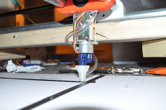


The gantry head includes a spring loaded solenoid (custom modified to meet design requirements), a servo, and a 3D printed vacuum head.
The full system measures slightly over 3X5 feet. The gantry arm can be seen on the far side with its triangle for cable routing. The electronics can be seen mounted on the close ledge.
3D printed linear slides offer a good compromise between friction, accuracy, cost, and simplicity. Seen in white is the linear slide for the long axis. Seen in orange is the linear slide for the short axis.
The camera mount allows overhead images to be taken during operation
Electrical conduit was used as rails for the linear slides. It was attached to the wood using screws, after a hole was drilled in the top. These holes do not affect the motion of the linear slides.

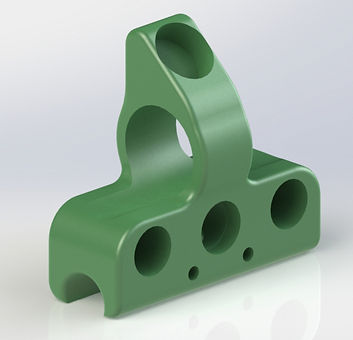
Final gantry design: all moving parts
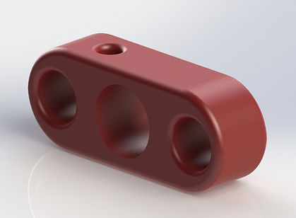
3D Printed Linear Slides